Interactive Requirements Engineering (iRE) is a new approach of requirements engineering. In order to systematically manage the system requirements during the modeling process, the iRE approach aids the requirements analyst derive a formal specification from a set of system requirements semi-automatically and interactively with the requirements analyst. An overview of the iRE approach has been published as a conference paper (WCCS 2014). This tool is for demonstrating the concepts of the iRE framework. It is distributed as a plugin for Eclipse, which utilises the built-in modeling frameworks of Eclipse such as EMF and GMF.
This iRE tool includes a Change Management Framework (CMF) for supporting modeling of a new large-scale system. This framework works on top of a Semantic Network Model (SNM) that records the acceptance decisions about inclusion of the given requirements and their relations into the system. Using this tool, a requirements analyst will be able to create the BTs of the software system, and a Semantic network model from these BTs. The requirements analyst will experience a new and effective approach of managing the sytem requirements during the modeling process.
How to install the iRE tool:
- Download a fresh installation package of Eclipse.
- Open Eclipse, go to Help->Install New Software…
- Add a new update site: http://www.beworld.org/BE/resource/tools/ire/update/
- Select both Graph BT and Semantic Network Model features, and follow the prompts to install the tool.
The components of the iRE framework, including all the dependencies, will be downloaded and installed automatically.
Quick Start:
- Download the Behavior Trees (BTs) of an example software system called Security Alarm System (SAS).
- Create a new project from Eclipse (General project), let’s say you named it as ‘sas’.
- Copy the downloaded .graphbt files into the folder. A .graphbt file represents a Behavior Tree, which has been created from the requirements of the SAS (The requirements of the SAS can be found here).
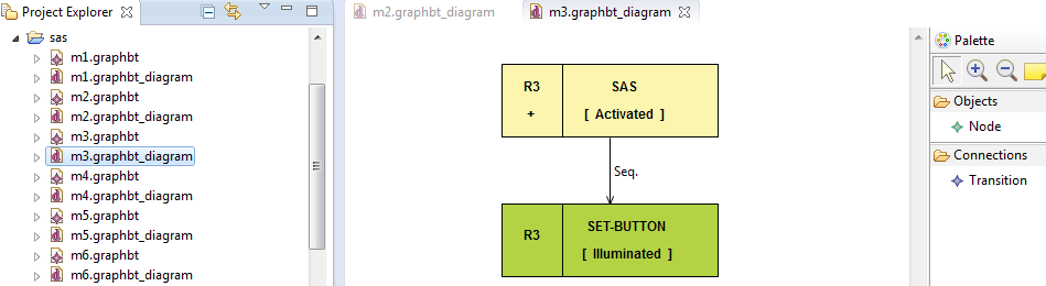
The Graphical Editor for the BTs of the Security Alarm System
- Right-click on each of the .graphbt files, and select ‘initialise graphbt_diagram diagram file‘. You may want to have a look on the .graphbt_diagram files, they are opened in an editor for BTs. The palettes, on the right hand side, for Node and Transition can be used to create BTs. The attributes of the nodes and transitions can be edited from the ‘Properties’ view.
- To create a Semantic Network Model (SNM) from these BTs, right-click on the project folder (sas), and select ‘Generate SNM‘ menu item. The relationships between the BTs will be determined, and an SNM will be created from the interrelated BTs. Refresh the project folder, and then you will see a new file called ‘sas.relations‘. This file is the model of the SNM created for the BTs of the SAS.
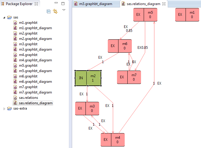
The Graphical Editor for the SNM of the Security Alarm System
- Right-click on the ‘sas.relations‘ file, and select ‘initialise relations_diagram diagram file‘. The SNM will be opened in a new editor for it. Modeling decisions can be performed on the model nodes and their relation edges.
- To select the initialisation model (the model that initialises the software system), right-click on that model in the SNM editor, and select Change Model -> Select as Init. For the SAS sample, m2 is the initialisation model. Similarly, a model can be made as Non-Init.
- To normalise the SNM, right-click within the SNM editor, and select ‘Normalise SNM‘.
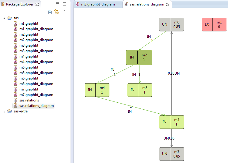
The Normalised SNM for the BTs of the Security Alarm System
- To change a model (addition, deletion or modification), right-click on the corresponding .graphbt file and select the corresponding actions (Add Model to SNM, Remove Model from SNM and Update Model in SNM).
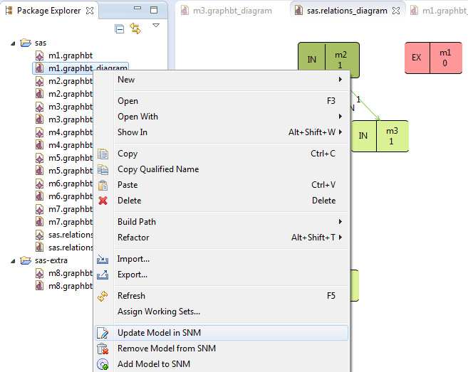
Updating the SNM for a modified BT
- To change a relationship status to IN (included) between two BTs, right-click on the corresponding relation in the SNM editor, and select Change Relation -> Include (IN). Similarly, a relation can be made as UN (Undecided i.e. to be decided later) and EX (Excluded).
- To integrate all the BTs into one BT, right-click on the ‘sas.relations‘ file, and select ‘Integrate Models‘. If the SNM is well-formed, an integrated model named ‘integratedBT.graphbt’ will be created. You can see the file by refreshing the project folder again. To open the integrated BT in the BT editor, right-click on that file and select ‘initialise graphbt_diagram diagram file‘.
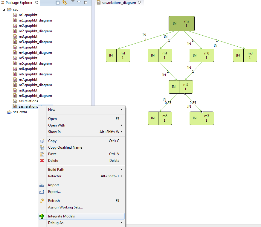
The Well-formed SNM for the BTs of the Security Alarm System
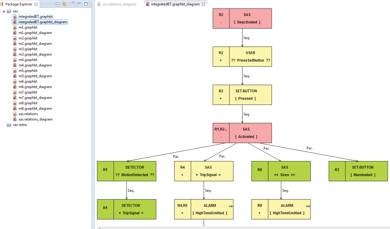
The integrated BT for the Security Alarm System
The detailed instructions and functions are described below:
1. Editor for Behavior Trees:
This tool provides a GUI for creating BTs by drag-n-drop facility. After creating the diagram files, the palettes from the right hand side can be used to create a BT.
1.1 How to create a new BT file:
- Right-click on the project folder, choose New->Examples->Graphbt Diagram and click Next.
- Provide a name for the Graphbt Diagram (e.g. m1.graphbt_diagram) , click Finish. Two files (.graphbt and .graphbt_diagram) will be created.
The file having .graphbt extension keeps the model of the BT i.e. its nodes and transitions. And the other file having .graphbt_diagram keeps the diagram model.
1.2 How to create the nodes and the transitions (edges) of a BT:
- Open the .graphbt_diagram file. It will open the editor for creating the node and the transitions of a BT.
- For creating a BT node, select the ‘Node’ palette from the right hand side palettes and then click on an empty space in the editor. A BT node will be created.
- For creating a transition between two nodes (connecting them together), select the ‘Transition’ palette and then click-n-hold on the sourc node and release at the target node.
You can change the values of the attributes of that node from it’s ‘Properties’ view. If ‘Properties’ view is not action in the window, right-click on that node and select ‘Show Properties View’. Similarly, you can change the values of the attributes of the transition from it’s ‘Properties’ view.
2. Editor for a Semantic Network Model:
This tool also provides another editor for the Semantic Network Model (SNM). The underlying framework of the iRE tool named Change Management Framework (CMF) aids the requirements analyst keep the BTs and the SNM updated for any change performed on them. This tool also has another underlying framework called Models Integration Framework (MIF), which integrates all the BTs of the software system into one BT in accordance with the integration formula for BTs. The formalisation of the integration of BTs has been published in a conference paper (ASE 2014). Further, the relationships between the BTs are identified while creating an SNM out of them. The relationships depend on different integration strategies of the BT nodes, the details of which can be found in another journal paper (JSCSE 2013).
2.1 How to create an SNM from the BTs:
- Once all the BTs have been created, right-click on the project folder, and select ‘Generate SNM‘. An SNM, having .relations extension, will be created under the project folder. The tool will consider the .graphbt files only under the project folder. You may need to refresh the folder to see it.
- Right-click on the .relations file and select ‘initialise relations_diagram diagram file‘. The SNM will be opened in a new editor for it.
2.3 How to normalise the SNM:
- Open the .relations_diagram file, it will open the SNM editor.
- Right-click on a model node and select Change Model -> Select as Init.
- Right-click within the SNM editor, and select ‘Normalise SNM‘. The SNM will be normalised. You may want to rearrange the nodes by selecting ‘Arrange All’ menu item from the editor context menu.
2. 4 How to add a new BT to the SNM:
- Create a new BT file as instructed earlier.
- Open the SNM editor to set it as the active editor.
- Right-click on that file (either .graphbt or .graphbt_diagram) under the project folder, select ‘Add Model to SNM‘.
Note that after adding a new BT to the SNM, it will be updated. To see the updated SNM, press F5 button and save the editor data.
2. 5 How to remove an existing BT from the SNM:
- Open the SNM editor to set it as the active editor.
- Right-click on that corresponding .graphbt or .graphbt_diagram file, and select ‘Remove Model from SNM‘.
Note again that after removing an existing BT from the SNN, the updated SNM may need to be refreshed and saved.
2.6. How to update an existing BT in the SNM:
- Modify or update the BT from it’s corresponding .graphbt_diagram file.
- Open the SNM editor to set it as the active editor.
- Right-click on that corresponding .graphbt or .graphbt_diagram file, and select ‘Update Model to SNM‘.
An update of BT in the SNM means that the relationships between the updated BT and other BTs will be again calculated, and the SNM will be updated. Note that the updated SNM may need to be refreshed and saved.
2.7 How to change the type of a BT for the SNM:
A BT can be of two types, Init or Non-Init. An init model initialises the software system. Other models are Non-Init models.
- Open the SNM editor.
- Right-click on the model node in the SNM editor, select Change Model -> Select as Init or select Change Model -> Select as Non-Init.
After changing the type of a BT, the SNM will be updated accordingly.
2.8 How to accept, reject or decide late on a relation from the SNM:
- Open the SNM editor.
- Right-click on the relation edge, and select Change Relation -> Include (IN), Change Relation -> Exclude (EX) or Change Relation -> Undecide (UN).
After changing the relation, the SNM will again be updated accordingly.
2.9 How to integrate all the BTs into one BT:
- Open the SNM editor.
- Right-click on the .relations or .relations_diagram file, and select ‘Integrate Models‘.
If the SNM is well-formed i.e. all the models are integrable, this tool will create an integrated BT named integratedBT.graphbt under the project folder. To see the file, refresh the project folder. To open it in the BT editor, right-click on that file and select ‘initialise graphbt_diagram diagram file’. For each of the above change operations, the user will see the effects through the semantic network.
Note: The iRE approach has been filed as a patent (applied for). For further enquiries, please contact the author.
Contact:
Author: Kushal Ahmed
Email: kushal [dot] ahmed [at] griffithuni [dot] edu [dot] au